Marelli SAE701A Diagnose Terminals |
|
| << back |
This page contains traces of the diagnose terminal signals on the logic and power board of the Marelli SAE701A mapped ignition system. All trace screen shots contain the TDC and RPM sensor as reference, as well as ΦM (zero crossing of the TDC sensor signal). TDC and RPM signals were created with a Pumpkin Inc. ICS2 ignition stimulator. For a first diagnose of a defective SAE701A ignition, apply TDC and RPM test signals at 2000 RPM and compare the signal traces on the different diagnose terminals to narrow down the circuit areas which might be faulty. |
Diagnose Terminals DepA (Power Board)The vacuum output signal of the APS Map Sensor is processed by hybrid RI.4 on the power board and then supplied as DC voltage (DepA) to the logic board. (This chart documents the relation between the applied vacuum to the Map Sensor and the resulting DepA control voltage) DepA without vacuum applied (~0V): 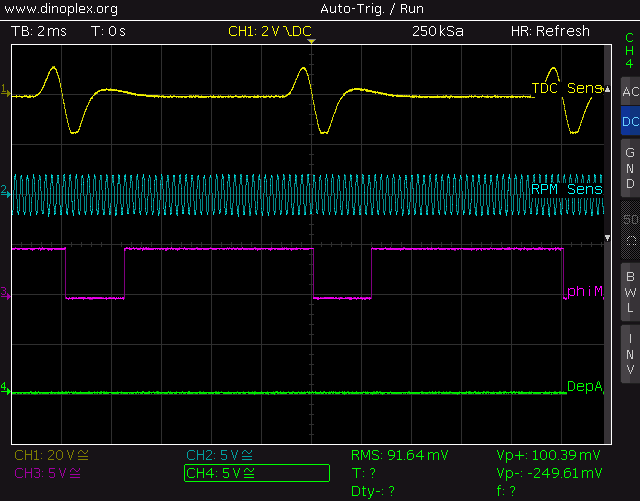 DepA with 325 mBar vacuum applied. The voltage of DepA has increased due to the applied vacuum: 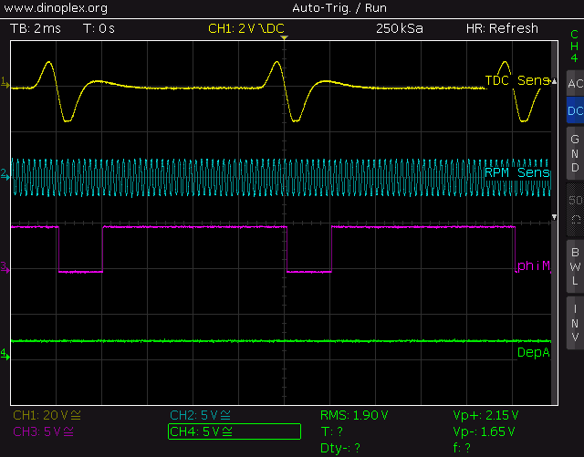 StTcA (Power Board) / τC (Logic Board) StTcA/τC indicates the start and length of the coil dwell cycle (coil charge time). StTcA and τC are identical. The StTcA/τC signal controls the base of the BUX37 ignition driver via ignition predriver TR14. Each time StTcA/τC goes low, a spark is issued.  PMS (Logic Board) Pulse signal, takes place when the TDC sensor signal crosses zero. Note that ΦM goes low at PMS. 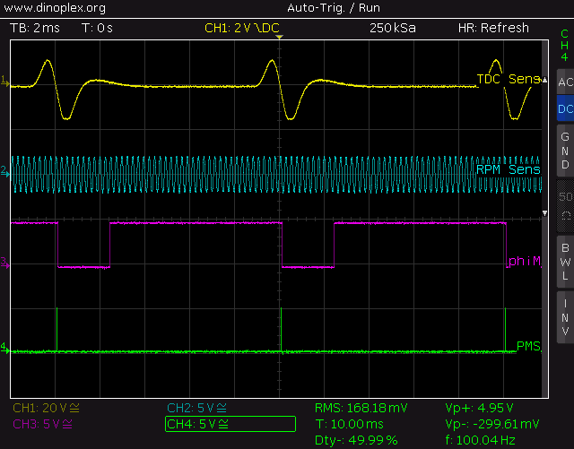 τN (Logic Board) Clock input for address counter. Als long as τN is low there is a positive voltage (ramp signal) on the left terminal of RT172. 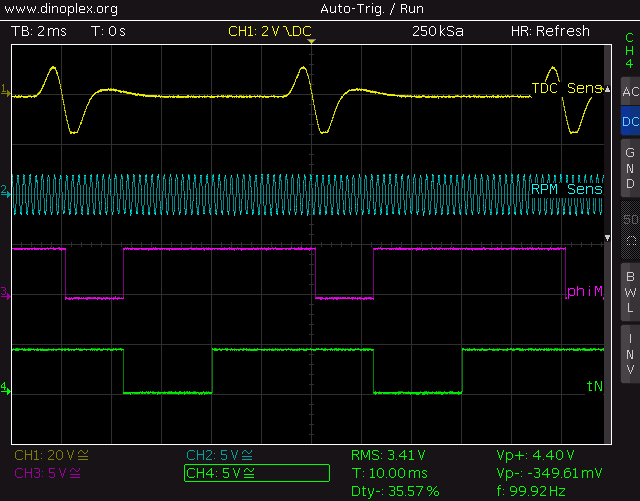 RT172, left terminal (Logic Board) Ramp signal, goes to input of hybrid RI.1 pin #4. This signal is created by TR100/TR101.  S1x2 (Logic Board) System clock multipled by two. The system clock frequency is based on the incoming RPM signal. 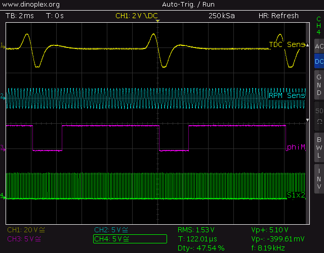 ST.τC (Logic Board) Pulse signal, indicates start of Coil Dwell Phase StTcA/τC. Note that ΦM goes high at ST.τC. 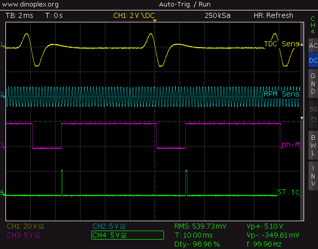 Ignition Driver Base (Power Board) Base input of BUX37 ignition driver, the duty cycle indicates the coil dwell phase. The ignition (spark) takes place when the signal goes low. 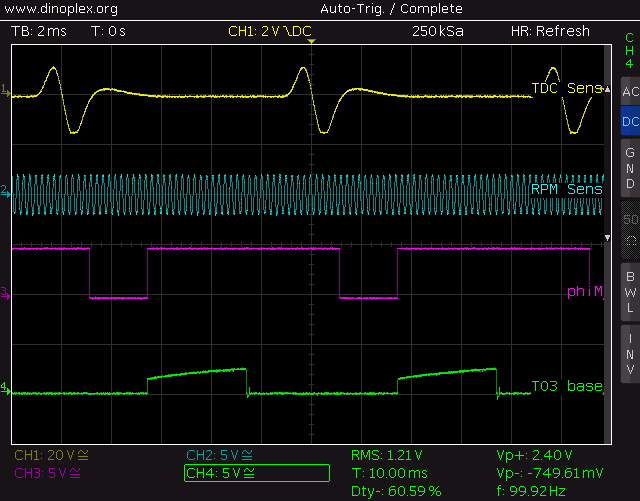 Tacho (Power Board) High voltage peak signal to drive the BMW M1 dashboard tachometer. The tacho signal is derived from the ignition driver output collector. 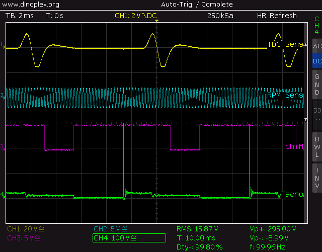 Hybrid RI.2 (Logic Board) Hybrid RI.2 processes timing and analog control signals. RI.2 Pin #1:  RI.2 Pin #2: 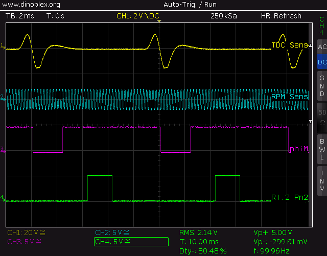 RI.2 Pin #4:  RI.2 Pin #5:  RI.2 Pin #6: 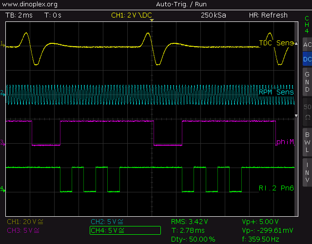 |
|