Veglia Speedo Type 1 Replacement Circuit Board
Project documentation for building and programming a replacement circuit board
V 1.1 8/2026, Copyright www.dinoplex.org, CC BY 4.0 (hardware & documentation) / GPL v3 (firmware) License
Introduction
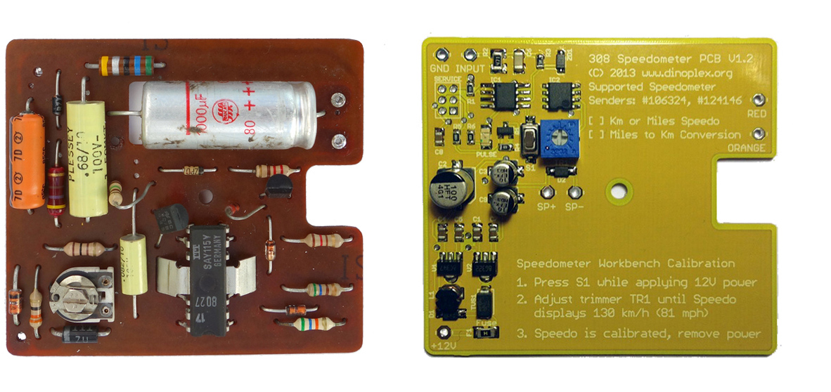
This project provides an open-source replacement circuit board for the Veglia Type 1 electronic speedometer used in various models of the Ferrari 308 family. Type 1 Veglia speedometers were the first electronic speedometers Ferrari used in their cars. This speedometer board design and its software have been successfully used in vehicles for many years and are considered mature.Designed as a direct replacement for the original electronics, the board preserves the original housing, mechanism, connectors, and appearance while replacing the ageing circuitry. It can be used to restore speedometers with defective original electronics or to reconfigure an instrument for a different application, such as converting an original Ferrari mph speedometer to km/h operation (this also requires a new dial face).
The downloadable project archive contains all design files, source code, and documentation required to manufacture, assemble, configure, program, install, and calibrate the replacement board.
Features
The supplied firmware source code supports multiple operating modes as compile options, including:
- Normal Mode: direct plug-and-play replacement of the original Veglia Type 1 electronics for miles or km/h speedometers
- Conversion Mode: conversion of mph speedometers to km/h operation (also requires a new km/h faceplate).
- Transitional Mode: support for transitional speedometer versions using the later Type 2 speedometer sender, which outputs twice the number of speed pulses
- Configuration support for custom tire sizes in addition to the already supported 205/70 VR14, 220/55 VR390 TRX, and 225/50 R16 tires
The firmware features a doubled coil pulse rate for smoother, jitter-free needle movement at low speeds. The firmware also includes an integrated calibration generator for the speedometer needle, allowing you to accurately calibrate the displayed speed after the installation of the board.
Compatibility
This project supports Veglia "Type 1" speedometers used in Ferrari 308 family of vehicles:
- Ferrari 208/308 GT4 EU & US, 1974-1980
- Ferrari 208/308 GTB/GTS EU & US 1976-1980
- Ferrari 308 GTSi/GTBi US 1980-1981
- Ferrari 308 QV US 1982
Type 1 speedometers can be recognized by their triangular warning lights for the turn indicators and by the lowest odometer digit, which advances in small steps rather than moving smoothly. If you have access to the paper label on the side of the housing, the marking “GEN 68 1005” also identifies a Type 1 speedometer.
Later models from 1982 onward, including the European Ferrari 308 GTBi/GTSi, Ferrari 308 Quattrovalvole (QV), and all Ferrari 328 GTB/GTS models, use a new Veglia speedometer with Type 2 or Type 3 circuit boards. Those are not compatible with a Type 1 circuit board.
Project Contents
The project archive includes:
- PCB Gerber files for manufacturing the circuit board
- Bill of Materials (BOM) for the electronic components (SMD, THT)
- Embedded firmware source code, Makefile, and prebuilt firmware images
- Firmware configuration and programming instructions
- Installation guide with photographs
The README file provides an overview of the project structure and serves as the starting point for the documentation.
Building the board
The replacement board can be built in four straightforward steps:
- Manufacture the board using the supplied Gerber files, as example by JLCPCB, PCBWay or OSH Park
- Source the electronic components listed in the Bill of Materials from companies such as Digi-Key or Mouser
- Assemble the PCB, either manually or through a professional PCB assembly service.
- Inspect and electrically test the completed board, then flash the firmware.
Firmware
The archive contains the complete firmware source code together with the required build system and documentation.
Before compiling the firmware, select the appropriate configuration for your speedometer, including the operating mode and, if required, the rolling circumference. The resulting firmware can then be programmed into the microcontroller using a supported Atmel programmer.Installation and Calibration
An illustrated installation guide explains how to replace the original circuit board and install the new assembly. After installation, the speedometer should be calibrated before being returned to service.
The odometer (ODO) is calibrated automatically using the configuration setting for the rear tire rolling circumference.
The speedometer needle must be calibrated after the new circuit board has been installed. To enter calibration mode, place a jumper on the marked 3×2 pin connector and then apply power to the speedometer. The circuit board will automatically enter calibration mode and simulate a vehicle speed of 130 km/h (81 mph). Adjust the trimmer on the circuit board until the speedometer needle indicates 130 km/h, or 81 mph on an mph dial face.
The calibration is then complete. Remove the jumper before installing the speedometer in the vehicle.
Licensing
The hardware production files, and documentation, are released under the Creative Commons Attribution 4.0 International (CC BY 4.0) license. The embedded firmware and associated source code are released under the GNU General Public License Version 3 (GPL v3).
Both the hardware and software may be used, modified, manufactured, and distributed commercially, provided the terms of the respective licenses are observed.
Downloads
Current Version: Download Archive 1.9