| |
Introduction
The speedometer sensors discussed here are inductive proximity sensors. They generate an electromagnetic field that is influenced by a passing ferrous metal object, such as a reluctor or a gearbox gear tooth. When a metal object passes in front of the sensor, the magnetic field changes, causing the onboard transistor circuit to switch the output signal to a low state.
The electronic circuit itself is simple and easy to repair, and all required components are readily available from electronic component suppliers. The main challenge is opening and resealing the metal housing without damaging the crimped edge. Since replacement sensors cost several hundred euros at the time of writing, attempting a repair is often well worth the effort.
Sensor Types
Type 1 sensors feature a short piece of speedometer drive cable inside the locking nut, with this design the speedo sensor can be mounted to a standard gearbox by replacing a traditional speedometer cable. The short speedometer drive cable ends in a small reluctor wheel inside the speedo body. Type 1 sensors send four pulses per full turn.
Type 2 sensors have a more modern design without any moving parts, they are directly mounted into the gearbox, adjacent to a gearbox wheel.
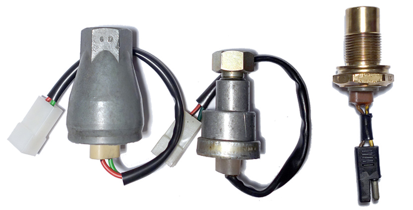 |
Type 1 (First Version)
Veglia 68 1005
Ferrari #106324
|
Type 1 (Second Version)
Veglia 68 1041
Ferrari #124146
|
Type 2
Veglia 68 0517
Ferrari #116987, old connector (shown)
Ferrari #149095, new connector
|
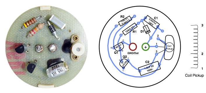
Type 1 Sensor, First Version 1974-1976 (Veglia 68 1005, Ferrari #106324)
This is the first Veglia speedo sensor design, it has been superseded by 68 1041 in 1976. Both sensors are interchangeable.
The earliest cars to use this sensor were the Ferrari 365 GT4 BB and the Ferrari 308 GT4, making them the first production cars ever to feature an electronic speedometer.
A common problem is oil seeping in through the speedo drive able seal, the oil can then damage capacitor C1 or C2.
Disassembly
Gently bend the crimped border upwards (the body material tends to be somewhat brittle), then remove the ring and white cover/wires with the circuit board below for doing a repair. To remove the circuit board from the white plastic cover you need to unsolder the two wires in the middle of the circuit board.
Sensor Circuit Board & Diagram
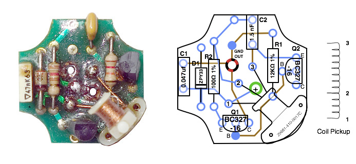
Type 1 Sensor, Second Version 1976-1980 (Veglia 68 1041, Ferrari #124146)
This sensor type replaced the previous Veglia 68 1005 sensor, both have the same circuit, speedo cable stub and nut, but a different body design. Early versions had the red/black stripe (signal) and green (+12V) wire colors of the previous type 1 sensor, later sensors changed to brown (signal) and yellow/black (+12V) wire colors.
Disassembly
For access to the circuit board the top of the crimped ring needs to be gently levered off, then the wire and white plastic cover/wires with the circuit board can easily be removed for repair. To remove the circuit board from the white plastic cover you need to unsolder the two wires in the middle of the circuit board. The board/components are covered with a thin layer of silicone seal, which can be easily removed with a knife tip, small screwdriver or needle.
Sensor Circuit Board & Diagram
Type 2 Sensor 1980-1999 (Veglia 68 0517, Ferrari #116987, Ferrari #149095)
This is the third version of the speedometer sensor and is already similar in design to modern speed sensors. The Ferrari 355 and Ferrari 512M were the last Ferrari model to use this type of sensor. Both types (#116987, #149095) are identical but use a different electrical connector.
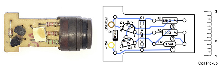
Unlike the earlier versions, this sensor has no moving parts. The pickup coil is embedded in the black plastic that seals the open end of the brass housing and is positioned to face a toothed gear wheel inside the gearbox.
Disassembly
The circuit can be accessed by first prying off the crimped brass border at the rear end of the sensor body, then remove the white top/circuit board/coil assembly from the sensor body by pushing in the black coil sensor at the open end. Heating up the sensor body with a heat gun helps if the sensor circuit is stuck.
Sensor Circuit Board & Diagram
Wire Colors
Early Type 1 sensors use red/black as the signal wire and green as the +12V wire.
Later Type 1 sensors and Type 2 sensors use brown as the signal wire and yellow/black as the +12V wire.
Testing
For a quick test you just need a 9V battery, a voltmeter and a 560 or 680 ohm resistor.
1. Connect the positive (+) terminal of the battery to the green wire (older sensors) or the yellow/black wire (newer sensors).
2. Connect one end of the resistor to the negative (–) terminal of the battery, and the other end to the red/black wire (older sensors) or the brown wire (newer sensors). Do not connect the battery's negative terminal directly to the sensor, as this could damage the sensor circuitry.
3. Set the voltmeter to the 0–10 V DC range. Connect the red probe to the yellow/black (or green) sensor wire and the black probe to the brown (or red/black) sensor wire.
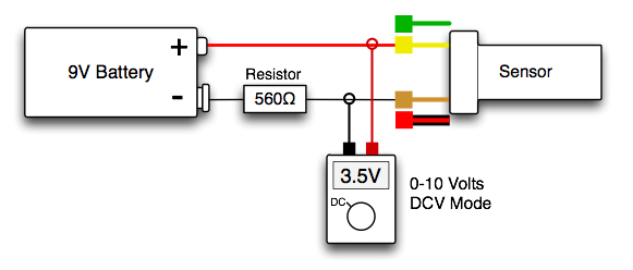
When slowly turning the wire stub on a type 1 sensor (or moving a metallic object in front of a type 2 sensor), you should see the voltage change between >3 volts (nothing in front of the sensor) and >8 volts (metallic object in front of the sensor).
If you see these values while testing, then the sensor is most probably perfectly fine.
→ If you don't see a change in the output voltage, then continue with the Repair section below.
Repair Procedure
1. Check all solder joints and components
Bad solder joints are not an uncommon problem, especially with the early sensors. Visually check all solder joints and carefully resolder them where necessary. Soldering flux helps considerably when handling corroded pcb traces. If you suspect a cold solder joint somewhere, wire up the sensor current test setup shown below and gently apply pressure to all components to see if the current changes.
Also check all components for cracks or other damage, replace where necessary.
Repeat the voltage test from above, or the sensor current test shown below.
2. Test the pickup coil resistance
Using a good multimeter in low resistance (Ohm/Ω) mode, measure the pickup coil resistance between the three solder pads (for location see the sensor circuit board diagrams above, you can measure the coil in situ). You should see the following values if the pickup coil is ok:
Solder Pad (1) - (2): ~0.1 Ω
Solder Pad (2) - (3): ~0.4 Ω
Solder Pad (1) - (3): ~0.5 Ω (sum of both windings)
If one of the (1) - (2) or (2) - (3) measurements return a much higher or open resistance value, try resoldering the coil wires to the solder pads. If this did not fix the problem, try rewiring the coil pickup if it's a type 1 sensor (see below).
Repeat the voltage test from above, or the sensor current test shown below.
3. Replace components
If solder joints and coil pickup resistance values are both fine, continue by exchanging the two BC327 transistors (Q1, Q2). If this did not fix the sensor, also exchange the two capacitors (C1, C2). If this still did not fix the sensor you might also try replacing both resistors (R1, R2) and the zener diode (D1), although these rarely break.
After repairing the board it is recommended to treat the component side with "Silicone Conformal Coating" spray for two or three times as a protection against oil and humidity before reassembling the sensor.
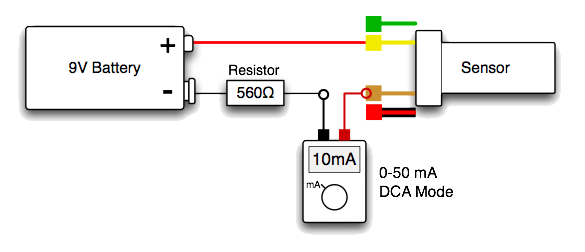
Sensor current test: A useful test during a repair is to measure the sensor's current consumption. When powered from a 9 V battery as shown below, a functional sensor typically draws 1–2 mA DC with no metallic object in front of the sensor, and approximately 10 mA DC when a metallic object is present.
Pickup Coil Repair
On type 1 sensors the pickup coil can be rebuild if broken. You need around 40 cm of silk insulated "litz" stranded wire, as used for rewinding high frequency coils and transformers. I am using 10x0,05 mm² HF stranded wire for pickup coil rebuilds.
The coil winding consists of two segments, one winding with a length of 5 cm between solder pad (1) and (2), and another winding with a length of 30 cm between solder pad (2) and (3) (see individual component diagrams above for locations of each solder pad).
Remove the old coil wiring from the pickup body.
Start from the left with the connection to solder pad (1), then wind 5 cm of wire clockwise around the pickup body.
Connect the wire to solder pad (2) and continue winding the remaining 30 cm clockwise. Solder the end of the wire to solder pad (3).
Fix the position of the coil windings with silicone spray or a bit of clear paint.
Circuit Diagram and Component List
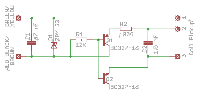
The collector of transistor Q2 is left open, this is correct as Q2 is wired up as a base-emitter diode.
Component List
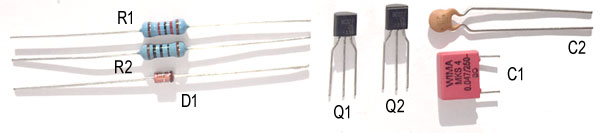
| # |
Value |
Part |
Part Description |
| 1x |
47 nF |
C1 |
47 nF (0.047uF) film capacitor, 100V, 105ºC |
| 1x |
1.5nF |
C2 |
1.5nF (1500pF) ceramic capacitor, 160V, 105ºC |
| 1x |
33V |
D1 |
BZV85-C33 Zener Diode, 33V, 1W |
| 1x |
12KΩ |
R1 |
12K Ohm resistor, 1%, 0.5W |
| 1x |
100Ω |
R2 |
100 Ohm resistor, 1%, 0.5W |
| 2x |
BC327 |
Q1, Q2 |
BC327-16 or BC327-25 PNP transistor |
Scope Signal Images
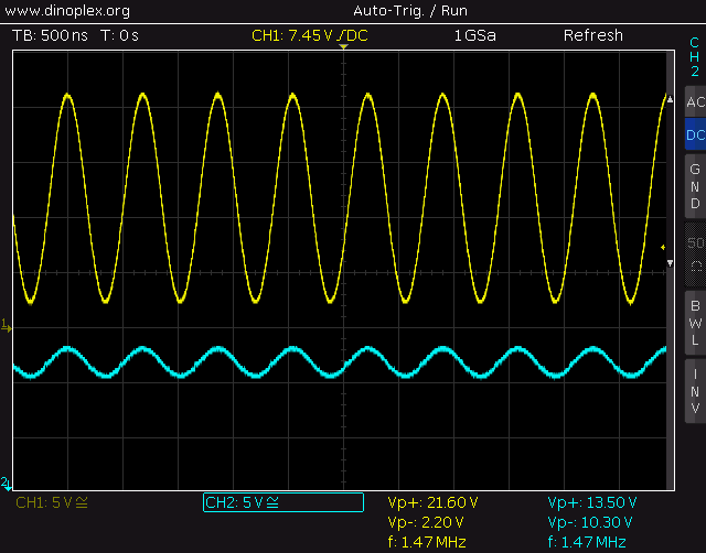
Magnetic field resonance at 1.47 MHz, measured at coil pickup wire: solder pad (3) (yellow trace) and solder pad (2) (cyan trace). With a metallic object in front of the sensor the signals above will change into a DC voltage (flat line).
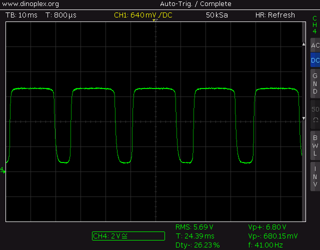
Sensor output signal (Red/Black or Brown wire) while simulating a drive.
|