|
|
| Quick Links: |
Introduction The Magneti Marelli Dinoplex was among the earliest commercially successful automotive capacitive-discharge ignition (CDI) systems and represented a significant milestone in the evolution of automotive electronics. Developed by Magneti Marelli in 1967 for Ferrari racing applications and first used on the Ferrari 312 F1, the system was subsequently adapted for the high-revving Dino V6 engine, with the Ferrari Dino 206 GT becoming the first production car equipped with a Dinoplex ignition system. Over the following two decades, Dinoplex systems were adopted across a wide range of competition and high-performance road cars, including the Ferrari 312 F1, Alfa Romeo Tipo 33/3, Dino 206 GT and 246 GT, Ferrari Daytona, Fiat Dino Coupé and Spider, Lancia Stratos HF, and Lamborghini Countach. About This website is an independent, non-commercial technical reference dedicated to historic Magneti Marelli ignition systems, including the Dinoplex, SAE701, and Microplex families, as well as Veglia Borletti instruments and automotive wiring diagrams. Its mission is to preserve and disseminate knowledge of the history, design, operation, diagnosis, repair, restoration, and installation of these historically significant systems for automotive historians, restorers, workshops, and auto-electricians. All articles, diagrams, technical analyses, and repair information presented herein are original works derived from archival research, reverse engineering, and hands-on restoration experience. No products, services, repairs, or other commercial activities are offered through this website. License All content is published under the Creative Commons Attribution-ShareAlike 4.0 International (CC BY-SA 4.0) licence and may be copied, shared, adapted, and reused, including for commercial purposes, provided appropriate attribution is given and derivative works are distributed under the same licence. |
Magneti Marelli Dinoplex C AEC 101 C/D/E (1968-1971)Models: AEC 101 C: Early type, first PCB version, metal switch, long wires with color coded plastic rings AEC 101 CA: Metal Switch, long wires with color coded plastic rings AEC 101 CB: Early types had a metal switch, later types bakelite switches, long wires with color coded plastic rings AEC 101 D: Metal switch, short wires with white plastic rings AEC 101 DA: Bakelite switch, short wires with white plastic rings AEC 101 DAX: Bakelite switch, short wires with white plastic rings AEC 101 E/EA: Short wires with a three terminal AMP connector, 12 cylinder engines (one unit per bank) Coil: Magneti Marelli BZR 205A (3 terminals) Replacement Coils: BZR 205A: Magneti Marelli BAE202B Cars with a factory installed Dinoplex: AEC 101 C: Early Fiat Dino 2.0l Coupe (from #02466 on) and Spider (from #0833 on), Abarth 2000 Sport Spider, Abarth 1300 AEC 101 CA/CB: Later Fiat Dino 2.0l Coupe and Spider, early Fiat Dino 2.4l Coupe and Spider AEC 101 D: Ferrari Dino 206 GT AEC 101 DA: Ferrari Dino 246 GT L Series AEC 101 DAX: Early Ferrari Dino 246 GT M Series, Ferrari Daytona GTB/4 Coupe US (two units) AEC 101 E/EA: Ferrari Daytona GTB/4 Coupe US (two units), Ferrari 365 GTC/4 US (two units), Ferrari 365 GT 2+2 US (two units) Installation Support: › Dinoplex C AEC 101 C/D/E General Wiring (Download) › Ferrari Dino 206 Wiring, '68 Europe (Download) › Ferrari Dino 246 L and early M Wiring, '69 Europe (Download) › Repair Support: › Dinoplex C AEC 101 Diagnose and Repair › Dinoplex C AEC 101 C/D/E Component and PCB Diagram (Download) › Dinoplex C AEC 101 C/D/E Replacement Parts (Download) › Dinoplex C AEC 101 Transformer Datasheet (Download) › Dinoplex C AEC 101 C (early type) Circuit Diagram (Download) › Dinoplex C AEC 101 C/D/E Circuit Diagram (Download) › Dinoplex C AEC 101 C/D/E Circuit Diagram in Color (Download) Notes: Dinoplex ignition units carry the type designation AEC, an acronym for the Italian Accensione Elettronica Capacitiva (“Capacitive Electronic Ignition”). Early Dinoplex C-series units, including the "C", "D" and early "CA" models, were equipped with a metal housing for the Normale/Emergenza selector switch. Later "CA", "CB", "DA" and "DAX" versions featured a bakelite switch housing instead. The Normale/Emergenza switch allowed the driver to select between the Dinoplex capacitive-discharge ignition system (Normale) and a conventional breaker-points and ignition-coil circuit (Emergenza), which served as a backup in the event of a Dinoplex failure On most installations, the tachometer operated only when the switch was set to Normale and was inactive in Emergenza mode. The later Dinoplex C "E" and "EA" models were supplied without the Normale/Emergenza switch and its associated wiring. These units can also be identified by the absence of the screw holes on the side of the housing that were used to mount the wire-retaining clips found on earlier "C" and "D" series units. ^top |
|
Magneti Marelli Dinoplex F AEC 102 A/B (1967-1970)Models: AEC 102 A: Ferrari AEC 102 AA: Ferrari, BRM AEC 102 B: Abarth, Alfa Romeo, BRM Coil: Magneti Marelli 5010114.1 (BZR 205A) Replacement Coils: 5010114: Magneti Marelli BAE202B Cars with a factory installed Dinoplex: AEC 102 A: Ferrari Dino 246 Tasman, Ferrari 212 E, Ferrari 312, Ferrari 312 B2, Ferrari 312 P/B, Ferrari 612 CanAm AEC 102 AA: BRM P153, BRM P160 , Ferrari 512 P, Ferrari 512S, Ferrari 512 M AEC 102 B: Abarth 3000 Prototipo, Alfa Romeo Tipo 33/3, Alfa Romeo Tipo 33 TT 12 Repair Support: › Dinoplex F AEC 102 Diagnose and Repair › Dinoplex F AEC 102 Component and PCB Diagram (Download) › Dinoplex F AEC 102 Circuit Diagram (Download) › Dinoplex F AEC 101 Transformer Datasheet (Download) Notes: The AEC 102 was the first Dinoplex ignition unit to enter production. Only a small number of units were manufactured, making it, together with the 101 DAX, one of the rarest variants in the Dinoplex C family. Internally, the AEC 102 used an earlier and simpler electronic design than the later Dinoplex C models, with correspondingly different PCB and component layouts. The enclosure was largely identical to that of the earliest Dinoplex C units, but lacked the Normale/Emergenza switch and instead featured three short leads terminated with a three-pin AMP/TYCO male connector. Some AEC 102 units were produced with the electronic assembly encapsulated in epoxy resin. Another distinguishing feature is the type designation, which was stamped into the cast aluminium housing. On later Dinoplex C units, the type designation was incorporated into the mould and appears as an embossed casting mark. The first two production series were finished in yellow paint, while the final series was left in its natural aluminium finish. Original units can be identified by the stamped type designation, the correct style of printed markings, and the proper serial number application. ^top |
|
Magneti Marelli AEC 103 A/B/BA (1970-1975)Models: AEC 103 A: Blue label, 6-8 cylinder engines, Fiat, Ferrari, Lancia, OEM, Aftermarket AEC 103 B: Red label, 2-4 cylinder engines, Fiat, OEM, Aftermarket AEC 103 BA: Green label, 2-4 cylinder engines, Emergenza/Normale connector, Aftermarket Coil: Magneti Marelli BAE 200A, BAE 201A, BAE 203A (replaced BAE 200A/BAE201A from 1973 on) Emergenza Coil: Magneti Marelli BZR 201A (satin matte black), BZR 202A (cadmium plated) Replacement Coils: BAE200A, BAE201A: MSD 8200 or MSD 8202 BAE203A: None available, revert to a separate Normale and Emergenza Coil setup BZR 201A, BZR 202A: Bosch Red (0 221 119 030), install with original Marelli Resistor or Bosch 1.5 Ohm resistor Cars with a factory installed AEC103: AEC 103 A: Ferrari 365 GTC/4 US (two units), Ferrari 365 GT4 2+2 US (two units), Ferrari Daytona GTB/4 Coupe US (two units), Ferrari Daytona GTS/4 Spider US (two units), Ferrari Dino 246 GT M/E Series and GTS, Ferrari 512 BB LM (two units). Fiat Dino 2.4 Coupe and Spider, Fiat 124 Coupe BC1 1600 and 1800 (factory option), Fiat 124 Spider 1600 Sport (factory option), Fiat 130 (factory option). Lancia Stratos HF Stradale. AEC 103 B: Fiat 124 Abarth Rally (factory option), Lancia Montecarlo S3 Installation Support: › Dinoplex AEC 103 A/B General Wiring (Download) › Ferrari Dino 246 Wiring, '70 Europe, two terminal connector (Download) › Ferrari Dino 246 Wiring, '72 Europe, three terminal connector (Download) › Ferrari Dino 246 Wiring, '73 Europe, six terminal connector (Download) › Ferrari Dino 246 Wiring, '71 US, two terminal connector (Download) › Ferrari Dino 246 Wiring, '72 US, three terminal connector (Download) › Ferrari Dino 246 Wiring, '73 US, six terminal connector (Download) Repair Support: › Dinoplex AEC 103 A Component and PCB Diagram (Download) Notes: The Marelli AEC103A ignition unit was produced between 1970 and 1975, with an additional production run manufactured in 1978. Units from the later batch can be identified by their enclosure casting, which lacks a serial number and typically exhibits a rougher finish than the original production series. A variant designated AEC103BA was equipped with two connectors, allowing straightforward switching between Normale operation and the Emergenza backup ignition mode. All AEC103-series units were encapsulated in epoxy resin. While this provided excellent protection against vibration and moisture, it also makes inspection, diagnosis, and repair of the internal electronics extremely difficult. ^top |
|
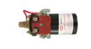
Magneti Marelli AEC 106 Raceplex "Ignition Sistem For Racing Car" (1975-1980)Models: Long Chassis, Coil on the right side Medium Chassis, Coil on the left or right side (5010564) Short Chassis, Coil integrated Coil: Magneti Marelli 5010343 Replacement Coils: 5010343: Marelli BAE202B (longer coil body) Cars with a factory installed Raceplex: Ferrari 312 T2, Ferrari 312 T3, Ferrari 312 T4, Ferrari 312 T5, Ferrari 126 CX, Ferrari 126 CK, Ferrari 126 C2, Ferrari 126 C3, Lancia Stratos Turbo G5, Fiat 131 Abarth Rallye Group 4 Repair and Calibration Support: › Raceplex Component and PCB Diagram (Download) › Raceplex Circuit Diagram (Download) › Raceplex Transformer Datasheet (Download) › Raceplex Rev Limiter Component and PCB Diagram, Calibration (Download) Notes: This rare, custom-built Dinoplex ignition was developed for Formula One racing applications and was deployed from 1975 onwards. In addition to its motorsport use, the unit also served as a replacement for the earlier AEC102 ignition, including installations in vehicles such as the Alfa Romeo T33/3.
Internally, the ignition is based on an early version of the circuitry later used in the AEC104B. This suggests that Magneti Marelli evaluated the new design in racing applications before introducing it as a production model.
Alongside the racing version, an OEM variant was also produced. This model featured an unpainted aluminium enclosure and a "Raceplex" label on the rev limiter module. Available evidence suggests that this version was marketed as an aftermarket performance ignition system. |
|
Magneti Marelli AEC 104 BW/BK/B-660/B-780
|
|
 |
Magneti Marelli SAE701A BMW M1 Ignition
|
 |
Magneti Marelli Microplex Ignition
|
Magneti Marelli Distributor S125
|
|
Ignition Replacements and UpgradesBosch High Power Ignition › Bosch setup with dwell control for Ferrari & Fiat Dino, Lancia Stratos (Optical Trigger) (Download) Black Stallion BSM › BSMpdi programmable electronic ignition, wiring for the Ferrari Dino 246 GT/GTS (Download) › BSMpdi programmable electronic ignition, wiring for the Fiat Dino Spider (Download) Lumenition › Lumenition Optronic Setup for Ferrari & Fiat Dino, Lancia Stratos (Download) MegaJolt › Megajolt programmable electronic ignition, wiring for the Ferrari Dino (Download) › Megajolt programmable electronic ignition, wiring for the Fiat Dino Spider (Download) MSD › MSD 6A setup for Ferrari & Fiat Dino, Lancia Stratos (Download) › MSD 6AL-2 setup for Ferrari & Fiat Dino, Lancia Stratos (Download) Winterburn › Winterburn CD Ignition setup for Ferrari & Fiat Dino, Lancia Stratos (Download) ^top |
|
 |
Ignition CoilsCoil Repair/Diagnose information › Magneti Marelli BZR205A Diagnose Printing Templates for Restoring Magneti Marelli Ignition Coil Labels › Magneti Marelli BZR205A Print Template (Download) › Magneti Marelli BAE200A, BAE201A, BAE203A Print Template (Download) ^top |
InstrumentsSpeedometer › Veglia Speedo Sensor Diagnose and Repair Tachometer › Universal Tacho Circuit Board Replacement ^top |
|
Car Wiring DiagramsFerrari Dino 246 GT Wiring DiagramsDiagnostic Wiring Diagrams with color coded Wire Groups for Quick Fault Diagnosis Dashboard Wiring Diagram with color coded wires for the Ferrari Dino 246 GT Relay Board Wiring Diagram with color coded wires for the Ferrari Dino 246 GT E-Series Lancia Stratos Wiring DiagramsA fully redrawn and enhanced color wiring diagram for the Lancia Stratos HF Stradale, available as a PDF download in three languages. The diagram covers the electrical system of the road-going Stratos HF, with all wiring shown in color.› Lancia Stratos Wiring Diagram — English (Download) › Lancia Stratos Schema Elettrico — Italiano (Download) › Lancia Stratos Schaltplan — Deutsch (Download) ^top |
|
| Questions, additions and requests: info@dinoplex.org | |
| Many thanks to Magneti Marelli, Bosch Automotive Tradition, Matthias Bartz, Margit and Leo Aumüller, Hans Uhlmann, Chris Hrabalek, Luca Savarro, Ola Kristofferson, Uwe Boos, Andrew Kalman, Alex Hagemann, Paul Rosche and Udo Sparwald | |
Imprint & DisclaimerThis website is provided as an independent technical reference for historical and educational purposes. While reasonable efforts are made to ensure the accuracy and currency of the information published herein, no guarantee is given as to its accuracy, completeness, reliability, or suitability for any particular purpose. Visitors who use this website or rely on any information contained herein do so at their own risk. To the fullest extent permitted by applicable law, the operator of this website shall not be liable for any loss, damage, or expense arising from the use of, or reliance upon, information published on this website. Nothing in this disclaimer shall exclude or limit liability where such exclusion or limitation is prohibited by applicable law. |
